3 way loudspeaker series network

This loudspeaker system is based on loudspeaker units from the other 3 way loudspeaker system that I have made.
I have used Vifa PL22WR0908 as a bass driver, Vifa PL11WG0908 as a midrange driver unit and the Scanspeak tweeter:D2905/95000.

Each of these loudspeakers have been modelled acoustically and electrically for the mounting in the pyramid enclosure, and these models have then been used for simulating the characteristics of the total system.

I am currently using a design which includes 9 components and in a serially connected network.

The right loudspeaker
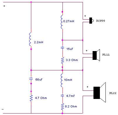
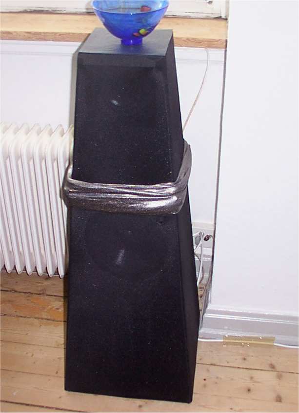
Right channel of the loudspeaker system.

Preface

The first design was implemtented in 1999 and since it has been one modification after another. Through the years, I have tried out many different filter configurations for this loudspeaker system:
  • I started out with 1. order, 2. order and 3. order Butterworth filters

  • Then I became aware of the problems about summation in three way systems and therefore I tried out The filler driver principle, introduced by B&O where the midrange is ideally 90 degree out of phase with the bass and tweeter (which are 180 out of phase in a 2. order Linkwitz Riley configuration).

  • Next tryout was the "Synkronfilter" proposed by DIY legend, Steen Duelund which is an extension of the Linkwitz Riley 4. order filter with a filler driver included. It's a filter where all drivers are working in-phase througout the entire passband. The downside is that extensive amounts of components are required, because each driver needs impedance compensation so that it ideally is seen as a pure resistive load by the filter network. In my opinion, the priciple design is ideal, offering very good radiational characteristics, but the component count will probably add up to 30!! Needless to say that will be costly, since good components are required in order not to add unwanted coloration to the sound.

  • And for the last two years, I have been working on solutions based on serial filtering configurations, -different 1st/2nd order serial networks consisting of as little as 6 components!!


Currently, I am a believer in the serial filtering scheme because it is component-inexpensive and therefore requires fewer lossy components (which can consequently be better). The possiblities are many: You can have in-phase coherence of the drivers, any filter order you like, impedance compensation networks can be included and the sound is often much more "forward", depending on the filter Q which is very freely chosen for each of the drivers.
In short: an inexpensive design that often sounds better than the sophisticated ones...

Modelling the Enclosure

This design is based on the enclosure that I used for my first 3-way loudspeaker system. However, a small modification has been made, since I moved the tweeter from the cement ball down inside the midrange enclosure. This means that the tweeter is not perfectly time-aligned with the midrange driver longer due to my current setup.

Schematic of setup
Schematic of the loudspeaker and how it is used in the setup.

This changed arrangement of the tweeter meant that I could alter the apperance of the loudspeaker slightly, which I think was a major improvement of the WAF. (Wife acceptance Factor) A picture of the left channel and my stereo system can be seen here

I modelled the responses (acoustical and electrical) of the loudspeaker drivers mounted in the enclosure using matlab. Using these and electrical circuit models made in matlab, I was able to simulate both the electrical and acoustical characteristics of the loudspeaker system

The bass driver.

PL22 in 50 liter enclosure
Simulated acoustical response of PL22 mounted in a sealed enclosure of 50 liters.

PL22 in 50 liter enclosure
Simulated electrical response of PL22 mounted in a sealed enclosure of 50 liters.

The midrange driver.


Simulated response of PL11
Simulated acoustical response of PL27.

simulated response of PL11
Simulated electrical response of PL11.

The tweeter.

The tweeter
Simulated acoustical response of Scanspeak 9500 tweeter.

The tweeter
Simulated electrical response of Scanspeak 9500 tweeter.

The filter network

In the design of the loudspeaker system, I used the models for the transducers which are depicted above. I wanted a system which was had a relatively constant acoustical frequency magnitude transfer function, a reasonably high impedance and a The circuit depicted below is what I came up with (twe tweeter is actually connected with opposite polarity as the bass and midrange, which I forgot when I made the drawing).
Schematic of the network
Electrical circuit diagram used in the loudspeaker system.

The electrical characteristics of this filter including the modelled electrical characteristics of the drivers is depicted below.
The electrical response
The electrical characteristics (with the tweeter connected in phase).

The impedance seen by the amplifier is not at all frequency independent due to the tweeter/midrange, but it is never the less higher than 4 Ohm for all frequencies.
The impedance seen by the amplifier
The impedance seen by the amplfier.

The acoustical output is relatively constant for all frequencies and the drivers work in phase for all frequencies.
The acoustical characteristics of the loudspeaker system
The acoustical characteristics of the loudspeaker system.